The A380 is a gigantic aircraft, but in structural and aerodynamics terms it is relatively straightforward

The key advances seen in the A380 lie in the engineering solutions behind the sheer size of the structure, the new materials that make it light enough to be operated profitably and the subtle influences of the first Airbus in which the airframe has been totally designed and optimised using computational fluid dynamics (CFD).

The vertical ovoid fuselage provided the best configuration for a high-capacity interior, and yet still fitted within the 80 x 80m (260 x 260ft) box that confined its development from the start. "There is no better fuselage configuration than that of a widebody on top of a widebody," says A380 programme senior vice-president engineering Robert Lafontan. "If you have a narrowbody mated to the top of a widebody (an A340/A320 hybrid was considered), then it is too restrictive. There is no room for growth. If you have a wider body then the evacuation rules make it uneconomical. A widebody on top of another widebody is also capable of being a good freighter," he adds.

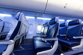
In its 555-passenger tri-class layout, the baseline A380-800 version can seat 96 business and 103 economy passengers on the upper deck and 22 first and 334 economy passengers on the main deck. Maximum width of the upper deck cabin is 5.9m (19ft 5in), versus 4m for the 747, while that of the main deck is 6.6m versus 6.1m for the Boeing.

For the first time on any Airbus aircraft, aerodynamic design of the fuselage was optimised in the presence of all the other airframe components using advanced CFD. Although the overall effect was more important for the wing, the process yielded a more than 2% reduction in aircraft drag. Of key importance was the design of the fuselage nose - a necessarily blunt feature because of the double-deck layout and the requirement to stay within the 80m box. Overall design was driven by drag, fuselage width and cabin acoustic considerations, and the result was wholly subsonic flow over the nose at around Mach 0.85, and freedom from shock waves up to M0.89.

"The front fuselage is high-value real estate, and we've done a lot of work there in terms of optimisation of the flow around the cockpit door and windows," says A380 aerodynamics director Frank Ogilvie. The mid-level flightdeck position was finalised in 1998 after first being proposed in 1994. The nose section was also slightly flattened with less sharp curvature to help boost nose-up pitching moment and trim.

Including the flightdeck and lower cargo hold, the nose section houses four separate decks. Laser beam welding (LBW) is used on the curved, pressurised bulkhead which seals the flightdeck floor and forward lower bulkhead from the large, unpressurised lower nose section housing the landing gear and weather radar.

The massive front fairing is constructed of a quartz fibre composite sandwich around the radome and aluminium. Not including Glare, composites make up 22% of the A380 by weight, says Jerome Pora, structures deputy director. Aluminium comprises 61%, Glare 3% and titanium and steel 10%, with surface protection and miscellaneous materials making up the balance.

Glare (see box pX) is used for the upper fuselage shells, crown and side panels, and is being studied for possible use in later models on the empennage leading edge because of its good bird strike capability. It is used for the upper sections of the forward upper fuselage, and the aft upper fuselage. Advanced AL2015/2024 aluminium alloys are used for the centre upper fuselage section, where its fatigue resistance and damage tolerance make it suitable for increased residual strength and preventing crack growth. LBW replaces rivets and saves assembly time and cost, says Pora. He adds that the concept may be extended from stringer-to-skin applications to entire fuselage skins.

Two small LBW skin panels are currently made for the A318, and "in the future we could have welding for clip to frame, panel to clip and panel to frame in the cockpit and centre fuselage panels", says Pora. Airbus sites at Nordenham, Germany, and St Nazaire, France, are developing simple repair techniques.

Weight-saving techniques have also been applied to the massive centre wing box. The top and bottom skin panels, front, centre and rear spar and upper skin panels are all composite, with aluminium used for the upper beam, floor struts, and supporting main frame structure. Most of the composites in the wing box are carbonfibre reinforced plastics (CFRP), while the aluminium sections are mostly 7000 series alloys.

The adjacent main landing gear bays are made from structurally reinforced machined panels with locally riveted stringers. Surrounding the entire section is a huge belly fairing extending from frame 34 by the No 1 door to the aft main cargo door at frame 82. The fairing is made up from around 100 composite panels with a lightweight honeycomb core. The equally outsized rear pressure bulkhead is also extremely lightweight for its 5.5 x 6.2m size. It is assembled from a CFRP dome and attached to the aft fuselage by a conventional circumferential milled aluminium butt-strap joint at frame 95.

Cargo deck floor beams are made from conventional aluminium AL7175T alloy, but for the main deck Airbus is finally able to incorporate the long-awaited, lightweight aluminium lithium Al-Li-C460/2196 material that is now mature, and cheap enough to use. Another structural innovation for Airbus is the use of CFRP composite (intermodulus fibre) floor beams for the upper deck. "We are also studying the introduction of titanium into seat rails, which some of our customers like in the 777 for corrosion reasons," says Pora, who cautions there is a weight penalty for the higher-density material.

Weight savings are also employed for the enormous wings, each measuring 36.6m from root to tip. To appreciate the sheer scale of the structure it is worth noting that the chord of the A380 wing at the root (17.7m) exceeds the span of one A320 wing by 3.2m.

The design itself draws on features from both the twin- and single-aisle Airbus families, and builds on a heritage reaching all the way back to the de Havilland Comet, Sud-Aviation Caravelle, BAC VC10 and VFW614. Unlike every Airbus wing since the A310, the A380 wing was not competed between the partners. Instead, "we decided to collaborate and chose jointly a mainstream design", says Ogilvie.

Aside from the 80m box constraint, the dimensions and shape of the baseline wing were affected by several restrictions. The taper ratio was constrained by wing area and root chord, the latter itself limited to less than 18.3m to comply with current FAA rules governing the maximum distance between exits. The crucial exits in this case are the forward doors on the upper deck, and the position of the escape slides over the leading and trailing edges.

The result is a large area wing of 845m2 compared to 524m2 for the 747-400. "The 80m box was defined by the infrastructure, otherwise we would probably be bigger in span rather than area," says Ogilvie, who adds that the A380 is "an extremely dense aircraft". Wing area is also determined by the relatively simple high-lift system consisting of single-slotted trailing edge flaps, leading edge slats and two-section drooped nose device. Flaps and slats are designed to provide a surprisingly low 140kt (260km/h) approach speed, some 16kt slower than the 747. The wing is also sized to provide a larger 1.3g buffet onset margin. "We needed to go straight to 35,000ft at maximum take-off weight without steps, so we will end up 4,000ft above the 747," adds Ogilvie.

The drooped leading edge nose device was added relatively late in the design process as part of changes to meet QC2 targets in 2002, and was based on a concept used in the 1960s on the initial Hawker Siddeley Trident model. The variable position leading edge droop is located by the wing root and aids take-off performance as well as providing a more positive stall. "We try and design the root end to stall first to give the aircraft a positive nose down so it recovers quickly," Ogilvie says. The new leading edge device replaces the original 3.6m of inboard slat.

The root section has inverse camber and the wing becomes gradually more aft-loaded further outboard. "We moved the loading inboard, which saved 3.5t in weight, but that caused wave drag penalties which we had to deal with - but the trade is worth it," says Lafontan. A further 2% drag improvement was realised through CFD-design-based spanwise changes in camber and twist. The work also helped minimise interference drag between the engine pylons and the wing, a hard lesson learned on the original A340 wing, which required substantial reworking.

Some 17 wing planform variations were studied while 25 wind tunnel "campaigns" have been conducted on 11 high-speed wing designs. "We have a final test in the European Transonic Windtunnel in Cologne towards the end of this year," says Ogilvie. Over the period the lift/drag ratio has been improved by 8% and Mach flexibility improved by 33%. The wing is positioned for a target centre-of-gravity range between 35% and 40%, further aft than any previous conventional airliner.

Sweep angle varies from 34.46° at quarter chord to 35.73° between the engines and 33.5° for the outboard section. "Our idea was to get as much sweep inboard and reduce sweep on the outboard as much as we could," he adds. Sweep angles between 30° and 35° were evaluated "which is substantially less than the 747 but more than the 777".

A key innovation of the A380 wing is an "active" load management system. Wing product engineering leader Rob Bray says the lateral fuel transfer system helps offset the long-term structural effects of the inboard loading philosophy. "As soon as we are into the climb we pump fuel outboard, and keep it outboard until on approach when we pump it back inboard." As with other Airbus models, the A380 will also benefit from Concorde heritage in having a longitudinal fuel transfer system to reduce cruise drag.

New wing structure

A major difference between the wing work on earlier Airbus projects and the A380 is the use of knowledge-based engineering techniques. "These have allowed us to compress the schedule and to get the design data through to manufacturing more quickly," says wing engineering integration centre vice-president Iain Gray, who adds that the bulk of design work for the first aircraft is done.

Other wing innovations range from the use of a completely new structural layout, and widespread use of new materials including composite ribs, to new manufacturing processes and construction principles. The flap tracks, for example, are a lower-weight hybrid of composite and aluminium. "Normally flap tracks would be a closed box beam, but what would be a single aluminium structure on one aircraft turns into a significant piece of structure on the A380," says Bray. "As soon as you scale up to this size of aircraft then everything gets bigger quicker."

The layout differs from earlier Airbus wings in having most ribs perpendicular to the rear spar, almost to the root. Aft of the auxiliary spar the ribs begin trending longitudinally towards the root where the inboard ribs are around 2.5m in depth. The forward spar is unusually kinked back towards the fuselage to make extra space in the cavernous leading edge section for the air conditioning packs, or as Airbus calls them, air generation units. Innovative, trussed, ribs have also been specially designed to support the huge depth of the leading edge at the wing root.

Airbus UK has also introduced an inside skin milling machine at its Broughton site which replaces the current faceting process, lowers the weight of each wing panel and improves the stringer attachment to the skins themselves. The ribs are 25% made from composite CFRP as a weight-saving measure - the first use of composite ribs as primary structure on this scale. The fixed leading edge is made from thermoplastics, while composite CFRP is used for the three-part ailerons, eight-panel spoiler set and outer flaps. Inner flaps are constructed from conventional aluminium skin and stringers, as are the two-section drooped nose devices.

The rear fuselage, tail cone and empennage has also been a focus for aerodynamic and structural optimisation work. The vertical tailplane, which towers 24.1m above the ground, follows in the established Airbus tradition of being essentially all-composite. Aluminium alloy is, however, used for the D- nose leading edge. The same basic construction technique is used for the horizontal tailplane, with the exception of a large titanium centre joint between the stabiliser sections.

Airbus A380-800 specifications

Length (m)

72.7

Powerplant - A380-800 Freighter


Height (m)

24.1

4 x Trent 977 or GP7277 (lb thrust)

76,500

Wingspan (m)

79.6


Wing area (m2)

845

Accommodation


High density seating

840

Weights


Typical 3 class seating

555

Maximum take-off (kg) -800

560,000

Upper deck

96B/103E

-800F (standard)

590,000

Main deck

22F/334E

-800F (option)

600,000

-800F capacity (containers)


Maximum landing (kg) - 800

386,000

Upper deck

17-25

-800F

427,000

Main deck

29-33

Maximum zero fuel (kg) -800

361,000

Lower deck

13

-800F

402,000

-800F volume (containers + bulk - m3)

948

Operating weight empty (kg - typical) -800

276,800


-800F

252,500

Performance


Volumetric payload (kg - typical) -800

66,400

Normal cruise speed (Mach)

0.85

-800F

152,400

Max cruise speed (Mach)

0.89

Fuel capacity (litres)

310,000

Max altitude (ft)

43,000

Powerplant - A380-800


Take-off length (m) at MTOW, sea level, ISA+15°C

2,990

4 x Rolls-Royce Trent 970 or

GE/P&W Engine Alliance GP7270 (lb thrust)


Design range (km) -800 with 555 pax

14,800

70,000

Design range (km) -800F with 150t payload

10,360

Source: Flight International