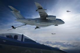
Airbus Military's airlifter has several things in common with its commercial siblings, sharing dimensions and composites technology that were pioneered for airliners

Structurally, the A400M presents perhaps the best example of a classic European design combining the basic utility and straightforward strength of a conventional aluminium monocoque fuselage with the advanced composite primary wing structure pioneered by the Airbus commercial line.

To provide the maximum internal volume to meet the European Staff Requirement, the cross-section is non-circular and derived from two distinctly different arcs. The upper arc effectively is based on the standard Airbus widebody 5.65m (222in) fuselage diameter, while the much wider lower arc is designed to provide an almost flat bottom for the fuselage and allow for a 4m-wide cargo floor. The two arcs are faired together to present a plump, pumpkin-like cross-section offering an internal height of 3.85m and an overall cargo hold volume of 356m3 (12,580ft3).

"The design began with the cargo box. We built a minimum fuselage shape around it, which was not circular," says A400M design integration vice-president Jean-Jacques Cuny. "When we did that we realised the upper diameter was only a few centimetres less than the cross-section of the A330/A340. So we decided to set the diameter to the same amount for commonality. Not a single frame is the same, but by sharing similar dimensions we can use many of the same parts of the manufacturing and assembly process such as the stretch-forming tools and panel-carrying trolleys."

The fuselage comes together as four main structural elements, including the nose section; forward fuselage barrel; centre fuselage with an upper section cutout for the wing to fuselage join; and the aft fuselage section with a large cutout for the 5.4 x 4m cargo ramp and its associated 8.1m-long rear cargo door.

Aluminium is used for the primary fuselage structure, including the skins, stringers, frames and floor beams, which are strengthened to withstand the heavy local loads of the cargo bay. Titanium alloys are used for the remaining high-load areas such as the wing-to-fuselage join, undercarriage mounting and windscreen. The only significant composite structures found in the fuselage are the large fairings around the wing and main undercarriage.

Aeromedical mission

The fuselage is designed to maintain an 8,000ft pressure altitude when flying at 37,000ft, and a 9,000ft pressure altitude when flying at 40,000ft. The structure is also capable of maintaining zero-feet cabin altitude up to 19,400ft for medevac operations, for which the A400M is designed to take up to 66 NATO standard stretchers. These will be mounted on a support structure attached to tie-down rings in the cargo floor. There will also be seating for 28 medical personnel on adjacent troop seats, while eight stretchers are provided as standard and can be stored on board.

Four passenger doors are built into the fuselage, two forward of the right-hand exit for emergency use only, and two aft that are for paratroop dropping. Two emergency exit hatches are also located in the roof of the flightdeck area and the cargo section, both of which allow access to the upper wing surface.

The commodious cargo bay is designed to accommodate up to 116 fully equipped paratroops seated in four rows. The two centre rows, each seating 30, are removable to open space for the main-deck cargo, while permanent sidewall-mounted foldaway seating for 28 is provided on either side. Four static lines are arranged down the length of the cabin to provide for paratroop dropping or, in the case of the main ramp, cargo parachute loads. Two electric winches are fitted to recover the parachute deployment bags and even parachutists who are still attached to the static line.

The cargo deck can carry nine 463L-standard (2.74 x 22.4m) military pallets, for which a fully integrated pallet/roller/restraint system will be installed in the floor. An optional kit for 3.17m-wide civil pallets can also be installed using the existing tie-down rings for support. An autonomous cargo handling system is also installed and uses power from a heavy-duty winch located beneath the deck on the centreline at the forward end of the cargo hold. The system will allow all the pallets and containers to be unloaded by a single loadmaster.

The ramp is a crucial aspect of the cargo system and is hydraulically actuated. The 5.4 x 4m-wide structure can be locked in several positions ranging from fully up to 12¡ down and can support up to 6t. Hydraulics also control the operation of eight latches on each side of the door, the aft bulkhead of which houses an attachment for three hydraulically actuated "toes". These can ether be stored in a vertical position on the ramp or disconnected and stowed on board for operations such as air dropping. As well as assisting with roll-on/roll-off loading, the toes will be used to extend the ramp during loading with palletised cargo.

Another cargo loading option still being evaluated is a 5t-capacity single-rail crane that would be mounted in the skin on the exterior of the fold-up cargo door. Once the door is recessed into the tail, the rail crane would allow loading of 2.44m-high military pallets and bulk loads from ground level and from truck height.

As well as regular palletised or containerised loads, the cargo deck is dotted with 400 tie-down rings, 250 of which will have a 4,540kg (10,000lb) load capacity, 60 with 11,350kg capacity and 90 with a 4,540kg limit. Overall, the interior is sized to house loads as varied as a semi-articulated truck to three armoured personnel carriers. It is tall enough to take two Eurocopter Tiger attack helicopters or one AS332 Super Puma.

Head room

Providing the optimum head-room was an important design feature, says Ronald Tietjen, head of the cargo hold component management integration team. "We know that the German air force has problems transporting some cargo with the Transall C160, such as unmanned air vehicles, which are mounted on a launching truck. To get the combination in or out of the aircraft, the soldiers have to deflate the tyres, which is most inefficient."

Contracts for most suppliers for the cargo-handling system are due to be decided by February 2005, with deliveries starting in late 2006. Decisions over the loadmaster controls are to be made over the same period and "although it could be an advantage to select the same suppliers for both, it is not essential", says Tietjen.

The loadmaster workstation will be located on the left-hand side of the nose section on the floor level of the cargo hold. The station provides the operator with displays of cargo-handling operations and system status, an interface with the aerial delivery system and aerial delivery functions management, such as weight and centre-of-gravity computation.

The loadmaster workstation also allows control of the cargo-hold systems in flight and on the ground, such as opening the cargo ramp and rear cargo door; a back-up station for the load ejection and gravity drop sequence initiation; jettisoning of the drogue or extraction parachute; the cargo winch operation; kneeling system, cargo hold lighting, oxygen, cooling, heating, ventilation and fire warning.

Looming over the fuselage is the large T-tail unit which rises to 8.02m, giving the A400M an overall height of 13.5m. The vertical tail is made up of a three-spar composite main torsion box with a detachable hybrid metal/composite leading edge and a one-piece carbonfibre-reinforced plastic rudder. Aluminium is used in ribs in the fin that support the hinge mechanisms for the rudder, which is actuated by two electro-hydraulic servos. The horizontal tail is moved by a screwjack trimming device that operates through a titanium alloy central joint in the middle of the structure.

Instability issues

The horizontal tail spans 19.03m, and is swept by a relatively sharp 32.5°, an increase of 7° over the original design. Sweep was increased late in the design phase after analysis hinted at instability during pushover manoeuvres with a forward centre of gravity. In addition, windtunnel tests suggested that icing could also be a problem and, rather than add complexity and weight with a de-ice or anti-ice system, "we decided to change the geometry and have an aerodynamic solution", says Cuny. The tail change also solves the stability question, he adds.

The wing forms perhaps the most advanced aerodynamic and structural feature of the aircraft, having been deliberately restricted in span and yet designed for both high lift and a wide range of speeds up to Mach 0.72. Spanning 42.4m, the wing is the largest composite structure of its type and is broad in chord (5.6m) with an area of 221.5m2. With a modest sweep angle of 15° (at the 25% mean aerodynamic chord point), the wing has an aspect ratio of only 8.1:1 and a taper ratio of 0.345.

"The span is a sort of compromise as we were required to stay as close as possible to the Lockheed Martin C-130 and C160," says Cuny, who adds that "ideally we would have liked another 2.5-3m". The wing is also a "slightly lower aspect ratio than we normally design at Airbus, but that means it is also a lighter structure and has higher fuel volume", he adds. Part of the reduced weight comes from the use of four engines, the outer pair of which provide bending moment relief.

Following on from the A380 design, the A400M wing has been developed using three-dimensional aerodynamic analysis techniques that result in a fine-tuned design with varying camber profiles from root to tip. "We use trailing-edge camber to distribute lift spanwise, and because the taper ratio is smaller than on other Airbus wings, it has allowed us to have slightly less camber on the inboard portion than on the outboard," says Cuny. The overall weight benefit of the design, which helps distribute more lift towards the tip, more than offset "what we lose out in terms of drag", he says.

A massive part of the early design work was focused on the integration of the wing with the flow from the turboprops. Having witnessed the interference and wing-drop problems encountered unexpectedly by Lockheed Martin in the early development of the C-130J, the A400M design team was anxious to benefit from the lessons learned. "We were worried about non-symmetrical stall like on the C-130J. But they just tested with one new engine so they didn't see it," says Cuny.

To attempt to offset any possible propwash problems early on, AMC persuaded the propeller supplier to release its normally unavailable three-dimensional digital definition data of the swept blades. This allowed computer modelling of the complex flow, which showed the requirement for a unique "handed" configuration in which the propellers counter-rotate on each wing. The resulting DBE, or "down between the engines" arrangement ensures a symmetrical airflow over each wing and results in significant downstream benefits, including a simpler flap system and smaller horizontal and vertical tail.

Simplified flap

"The swirl behind the prop is reducing the local angle of incidence behind the engine, which is where we have the highest aerodynamic loading because of the elliptical [lift] distribution," says Cuny. "This allowed us to simplify the flap system, which was originally due to be double-slotted. Instead, we went to a vaned flap with a dropped hinge mechanism, similar to the design used on the [McDonnell Douglas] DC-10," he adds. "The other benefit is a 17% smaller vertical fin, because the configuration is defined by the critical engine failure scenario. We also discovered during tests a beneficial effect on the horizontal tailplane, which is now almost 8% smaller."

Cuny admits the solution was expensive and cost "several tens of millions of euros", but says the long-term benefits will make it more than worth it, despite the increased logistics of supporting the counter-rotating engines. "We are saving in airframe weight, and that means the aircraft is of an overall smaller size. We also have a very clean stall," he adds.

Structurally the wings go well beyond the A380 in terms of composite use, the design incorporating composite skins, stringers and two main carbonfibre spars. Aluminium is used for the 25 ribs in each wing, the fixed leading edges, engine mounts and fuselage pick-up locations. "We did trade studies on everything, including the ribs, and although we made some composite ribs for the A380, we came to a cut-over point at which it made more sense to go for metal in this case," says Charles Paterson, head of the wing aircraft component management teams.

Source: Flight International