MIKE GERZANICS / SAN JOSE DOS CAMPOS, BRAZIL

Flight International test flies Embraer's 170, which is emerging at just the right time to fill a niche in the market for smaller regional jets

Embraer's success has been built on regional aircraft - first the EMB-120 Brasilia and now the ERJ-145 family. The Brazilian manufacturer is a leading player in a regional jet market that had been limited to aircraft with 50 or fewer seats, largely because of pilot contract limitations. But post-11 September economics have drastically altered the airline playing field.

In their continuing efforts to survive, major carriers are flying smaller aircraft on some routes as demand has fallen, and have shifted capacity to their regional partners. Some majors have won concessions from pilot unions allowing their regional partners to fly aircraft with more than 50 seats.

With the smallest offerings from Airbus and Boeing being nominally 100 seaters, a market opportunity has emerged in the 70- to 90-seat size range. Bombardier was first to market by stretching its 50-seat CRJ, but Embraer has taken the time - and incurred the expense - to develop an all-new aircraft.

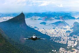
The first and smallest member of the 170/190 family, the 170, flew on 19 February 2002. Using six test aircraft, Embraer has completed almost 90% of the planned 1,800 flight-hour campaign to certificate the aircraft. Brazilian and European approval should be obtained by mid-year, with US certification following one to two months later. Flight International was able to evaluate the fourth pre-production 170 on an extensive flight test at Embraer's San Jose dos Campos production facility.

First impressions

The 170 does not look like a regional jet, an impression the flight would reinforce. The initial impression is of a cross between the Airbus A320 and Boeing 737, only slightly smaller. Capt Otavio Vaz Kovacs, who would act as safety pilot for our flight, pointed out two distinguishing features during the preflight inspection - the slender, 1.54m (5ft)-high winglets; and the lack of conventional angle-of-attack (AoA) probes. AoA is calculated from data supplied by four combined pitot-static "smart" probes.

Access to the large baggage holds is via manual doors fore and aft of the wing. The floor of each baggage hold is 1.52m above ramp level, which may allow bags to be loaded and unloaded without using a conveyor belt. Cabin access is via an external boarding ladder, but an internal airstair designed for autonomous operations will be available on production aircraft.

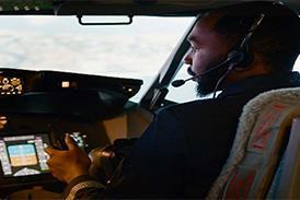
The 170's cockpit is open and airy, providing a seating position roughly the same height above the ramp as a 737's. Field of view out of the four large cockpit windows is good. As befits a larger class of aircraft, there is space to store an airline-size flight publications case outboard of the seat.

Aircraft system controls on the overhead panel use both rotary and illuminated pushbutton switches. As in the Embraer Legacy business jet, flown by Flight International earlier this year, a "dark cockpit" philosophy was used to design the overhead. When systems function normally, there are no lights illuminated on the panel.

The forward instrument panel is dominated by the five 255 x 205mm (10 x 8in) colour liquid-crystal displays of the Honeywell Primus Epic integrated avionics system. Each pilot has a primary flight display (PFD) and multifunction display (MFD), and they share the central engine instrument and crew alerting system (EICAS) display. Dual control-display units (CDUs) and cursor control devices (CCDs) on the centre pedestal are used to manage the capable dual flight management systems (FMS) and aircraft avionics.

Alignment of the dual global-positioning/inertial-reference systems took less than 4min. Pre-start checks were similar to those on other FMS-equipped aircraft and were accomplished easily. The tail-mounted auxiliary power unit was used to start the General Electric CF34-8E engines individually. Simply placing the rotary switch to the "start" position opened the appropriate pneumatic valves and allowed the full-authority digital engine control (FADEC) to initiate fuel flow at the proper time. Peak inter-turbine temperatures for the left and right engines were 520°C (970°F) and 550°C, respectively, well below the limit of 815°C. Idle RPM of 62% N2 was reached in under a minute for both engines.

Brake-by-wire

Idle power was enough to start the aircraft rolling once the parking brake was released. Brakes and nosewheel steering are electrically signalled. Centreline tracking on the taxiway was facilitated by the ±7° of nosewheel steering available with the rudder pedals, and 90° turns were accomplished using the side console-mounted tiller, which provides ±75° of nosewheel steering authority. The brakes were easy to modulate, with back-up braking via the centre console-mounted parking brake lever.

Flaps were set to position "2" - slats extended 15°, flaps extended 10° - in preparation for take-off. Once lined up on runway 15 and cleared for take-off, throttles were advanced to the take-off/go-around (TOGA) detent. As the engines spooled up to 93.2% N1, brakes were released. Acceleration was brisk as the relatively light aircraft - 29,806kg (65,710lb) with 5,510kg of fuel (maximum take-off weight is 35,990kg) - roared down the runway. Kovacs called "VR" at 124kt (229km/h) indicated airspeed, and about half aft-yoke travel and 16kg of force were required to reach the desired 12° nose-high take-off attitude. Ground run on the 21°C calm day was only 1,000m (3,000ft).

Landing gear retraction caused no change in pitch forces as the aircraft accelerated to 148kt (V2+10kt), where the take-off trim setting provided for trimmed flight. Flaps were retracted and an initial climb speed of 220kt - slower than the 250kt recommended below 10,000ft (3,000m) - was maintained to allow the photographic aircraft to catch up.

The first 45min of the flight were dedicated to aerial photography, providing invaluable time to appreciate the 170's handling qualities. Gentle turns, climbs and dives at low altitude and airspeeds in the 160-220kt range showed the control forces to be well harmonised in pitch and roll and markedly less than those in the Legacy. Power response from the FADEC-controlled CF34 engines was good and allowed for accurate position-keeping when the photo aircraft was in the lead position.

Impressive flight control

Although the 170 was not designed with formation flying in mind, the control forces and predictable aircraft responses generated by the fly-by-wire flight control system were pleasing.

After the photographic aircraft left to return to San Jose dos Campos, autopilot was engaged for a climb to a typical cruise altitude of FL310 (31,000ft). Flight-level change mode was used to climb the aircraft at 250kt to 10,000ft, where 290kt was selected using a knob on the glareshield-mounted flight guidance control panel. The heading select roll mode was used to stay within the test area's boundaries. The autothrottle kept the proper climb-power N1 setting during ascent. Passing FL270, Mach 0.72 was held for the rest of the climb.

The climb from 6,000ft to levelling off at FL310 burned 520kg of fuel and took 10min 45s, yielding an average rate of climb of 2,300ft/min (11.5m/sec). While final performance numbers are still being determined, at an estimated long-range cruise speed of M0.66, total fuel flow for the 27,836kg aircraft was 1,435kg/h, and 81% N1 was required to maintain 242kt indicated, yielding a true airspeed of 397kt.

Pushing the throttles to the TOGA detent accelerated the aircraft to M0.815, just below the maximum operating Mach number of 0.82. Retarding the throttles to 91% N1 held 302kt indicated, for a true airspeed of 488kt. Total fuel flow for this high-speed cruise condition was 2,250kg/h.

Before descending to FL180 for intermediate-altitude manoeuvres, a series of 2g 60°-bank turns at 290kt/M0.78 produced no buffet. Rolling wings level, I lowered the nose and descended at M0.82. Aircraft response to sharp control inputs in the pitch and roll axes was well damped, with no residual oscillations. With the yaw damper engaged, yaw motions excited by a sharp rudder input were quickly damped out. With the yaw damper off, a sharp rudder input revealed a snaky, lightly damped Dutch roll at one cycle a second.

Yaw damper back on, the speedbrake lever on the centre console was moved to the full up position. Light buffet accompanied deployment of the three flight spoiler panels on each wing as rate of descent increased by about 2,000ft/min. A slight pitch-up tendency was easily countered with forward yoke pressure. The speedbrakes were retracted and the descent continued until levelling off at FL180 to further explore the 170's flight control system.

Simplified fly-by-wire

The 170's electrically signalled flight-control system is simple yet elegant, incorporating some of the best characteristics of fly-by-wire while retaining the feel of a conventional aircraft. With the exception of the ailerons, which are connected to the control yokes by cables, all other control surfaces are not physically connected to the yoke or rudder pedals.

Yoke or pedal movement is detected by position transducers and fed to redundant flight control modules (FCMs) and actuator control electronic (ACE) units. The FCMs use air data-derived equivalent airspeed to determine the appropriate gain, and pass the resultant surface displacement command to the ACEs. The ACEs independently compute required surface displacement, as a cross-check to the FCMs, and implement the command.

Commanded displacement is optimised so that aircraft response feels the same throughout the flight envelope. With the exception of the AoA-limiting function in the pitch axis, actual aircraft response is not fed back to the flight control system, as it is in the Airbus A320 and Boeing 777 fly-by-wire systems. In essence, Embraer has replaced the mechanical connection between yoke/pedal and control surface actuators with electrical wire. It has also digitised the mechanical ratio-changing schemes employed in conventional flight control systems.

Control in the pitch axis is effected by both the electrically driven moving stabiliser and hydraulically actuated elevator. Actual elevator movement for a given yoke displacement is a function of equivalent airspeed and configuration.

Proving the concept

At FL180, I trimmed the aircraft at 300kt and took note of the thrust setting. Then I slowed the aircraft by 20kt and reset the power to the 300kt setting. About 2.5-5kg of aft yoke force was required to maintain level flight. Speeding up to 320kt - 20kt above trim speed - required 2.5-5kg of forward yoke pressure to maintain level flight.

I repeated this procedure at 200kt and at 140kt with gear and flaps down. As was the case for the 300kt trim point, slowing down or speeding up by 20kt from the trim condition required 2.5-5kg of aft or forward yoke pressure to maintain level flight. Over a fairly wide range of airspeed, control forces for off-trim-speed conditions were nearly identical.

The ailerons are conventional irreversible roll control surfaces operating at a fixed gain relative to lateral yoke displacement. The roll spoilers, three on each wing, are fly-by-wire. Spoiler displacement, like that of the elevator, is a function of equivalent airspeed. A series of rolls from 45° bank to 45° in the other direction used roughly half the available yoke displacement. In the clean configuration at airspeeds of 200kt, 250kt and 300kt, the times for the 90° bank-angle changes were all identical - 5s. Aircraft roll response is effectively linear in the heart of the up-and-away flight envelope.

In the yaw axis, the FCMs give full rudder authority, ±30° of displacement, only on the ground. Eight seconds after lift-off, rudder authority is reduced to ±20°. Actual rudder displacement for any pedal input is a function of equivalent airspeed and configuration. In the event of an engine failure, as determined by the FADECs, the thrust asymmetry compensator (TAC) puts in half the rudder displacement required to control the yawing motion. This displaces the available control-surface movement arc to give the pilot a full 30° of rudder in the appropriate direction, as well as providing a tactile cue as to which engine has failed. Yaw damper and turn co-ordinator functions are part of the autopilot, and not the fly-by-wire control system.

Preparing to stall

Kovacs called up the flight control synoptic page on one of the MFDs in preparation for a series of stalls. The first was in a clean configuration. I slowed the 26,900kg aircraft at 1kt/s in level flight. The pitch limit indicator, displayed on the PFD, closed in on the aircraft wings symbol and provided a visual cue of an impending stall. At 144kt, the stick shaker activated to indicate a stall. There was no buffet or other natural warning of the stalled condition. Control response in all three axes was good. Recovery was effected by releasing yoke backpressure and flying the aircraft out of the stall.

The next stall was in take-off configuration with gear down and flaps in position "4" (slats extended 25°, flaps extended 20°). This time a slight amount of aerodynamic buffet preceded the stick shaker's activation at 98kt.

Kovacs suggested I hold full aft yoke to keep the aircraft in a stalled condition. He pointed out the elevator position indicators on the flight control synoptic page. Even though the yoke was being held in a fixed position, the AoA limiting function of the fly-by-wire flight control system was actively moving the elevators to maintain the aircraft at its maximum usable AoA. Relaxing backpressure took the aircraft out of its stalled condition and disabled the AoA limiting feature.

The third and final stall was in a landing configuration, flaps in position "6" (slats extended 25°, flaps extended 35°). Although some rumble was felt when the flaps were fully extended, no aerodynamic warning accompanied the stick shaker's activation at 94kt. At the point of stall, control effectiveness in all three axes was good, allowing for a rapid and positive recovery to normal flight.

With 2,000kg of fuel remaining, we descended out of the test area for our return to San Jose dos Campos. First was a hand-flown instrument landing system approach using flight director guidance to runway 15. Approach reference speed with 1,770kg of fuel and flaps "6" was 113kt, and a target speed of 118kt was selected for the calm conditions. The minor pitch force changes caused by gear and flap extension were easily countered with the effective pitch trim system.

The flight director's guidance was easy to follow, and allowed the localiser and glideslope to be tracked accurately. About 59% N1 was required to hold the targeted approach speed. I began the flare manoeuvre at about 10ft above ground level, and retarded the throttles to "idle" at 5ft. The aircraft's response to pitch control inputs in the flare was quite natural, much like landing a 737. Touchdown and rollout were uneventful, using only toe brakes to slow the aircraft before turning off the runway.

Simulated single engine

Kovacs positioned the flaps to "4" and set the pitch trim as we taxied back to the approach end of the runway for another take-off. Once cleared for take-off, throttles were pushed up towards the take-off setting of 92% N1 and brakes released. At 101kt, Kovacs called V1 and simultaneously retarded the right throttle to idle to simulate an engine failure.

Roughly half left rudder displacement was required to keep the aircraft tracking down the centreline. At 110kt, I slowly rotated the aircraft to a 12° pitch attitude. A slight increase in left rudder input was required as the aircraft lifted off the runway. The gear was retracted and an initial climb was made at 130kt - 9kt faster than the computed V2 of 121kt. At 400ft, I used the flightpath marker in the PFD to help maintain level flight as the aircraft accelerated and flaps were retracted. About 80% of available rudder trim was required to zero out the single-engine yaw forces during the climb with take-off power set.

A visual circuit was flown to set up for the single-engine approach. Once on final, the gear was extended and flaps set to "5". Actual slat and flap positions at the "5" setting are identical to those of the "4" setting, the difference being that aircraft logic assumes a take-off condition for "4" and a landing condition for "5". Pitch attitude on final was nose on the horizon, slightly higher than the normal flaps "6" approach flown before. About 63% N1 was required to hold the target approach speed of 128kt. Less than 20% rudder trim was required on final to zero out yaw forces.

In preparation for a touch and go, Kovacs set the rudder trim to neutral on short final. With no rudder trim, less than 9kg of left rudder pressure was required to compensate for the asymmetric thrust. During the flare manoeuvre, rudder easily controlled the yawing motions as the good engine was retarded to "idle". The entire engine failure and single-engine approach profile was flown without the thrust asymmetry compensator (TAC) function, because it was not available on this developmental aircraft. Had TAC been available, the critical flight conditions easily handled in this pre-production 170 would have been even easier to cope with.

Once on the runway, the flaps were set to "4", pitch trim reset and power advanced on both engines. The aircraft lifted off after rotating at 130kt and we climbed for another visual approach. Once safely on downwind, Kovacs used flight test-specific switches to put the aircraft's flight control system into the back-up "Direct" mode. In production aircraft, Direct mode will not be crew-selectable; instead, automatic selection of the degraded mode will be announced to the crew via an appropriate caution message.

In Direct mode, spoiler roll-control gains are fixed and their speedbrake and ground roll functions disabled. Ailerons are always mechanically controlled, so their operation is unaffected. Pitch gains are fixed at one of two settings, based on the flaps being up or down. Rudder displacement is purely a function of pedal movement, but at speeds greater than 160kt, hydraulic pressure is reduced by a third. Reduced hydraulic power limits the rudder hinge moment and should prevent structural overstresses.

The last landing, flown in Direct mode, began with a visual final approach using ILS guidance to fly a 3° glidepath. An approach reference speed of 112kt gave a target speed of 117kt. The most remarkable thing about the approach was that it felt just like the first approach, flown in Normal mode. Again I initiated the flare manoeuvre at about 10ft, pulling the nose up to 5° above the horizon. After touchdown, rudder pedal nosewheel steering allowed accurate tracking of the runway centreline. Moderate toe braking alone - the thrust reversers having been disabled on this aircraft - was sufficient to stop the 25,356kg aircraft after a 1,100m ground run. During the 2h 41min flight, we burned 4,450kg of fuel.

Healthy competitor

Competition between regional jet manufacturers has been a boon for airlines and the travelling public. In the market for 50-seaters and below, Bombardier and Embraer's offerings are practically interchangeable. In the race to market 70-seaters, however, they have taken markedly different paths. Bombardier was first to market by stretching its CRJ; Embraer sought to develop a totally new aircraft family.

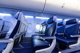
The Embraer 170 is the first small passenger jet to provide cabin accommodation equal or superior to those found in traditional mainline aircraft. A robust, simplified fly-by-wire control system allows the Brazilian company to field an aircraft with excellent flying qualities and should set the stage for the development of an entire family with nearly identical flight characteristics. Those carriers that have delayed their 70-seater acquisitions until the Embraer 170 is available may find it was worth the wait.

Source: Flight International