At the core of the 787’s revolutionary construction lie its mechanical systems, the development of which has forever changed the process of building a twin-engined widebody

With mechanical systems we’re looking at some big changes,” says Mike Sinnett, 787 systems director. “We have control-by-wire for most – including landing gear retraction, door retraction, steering and braking – versus the traditional approach, which is mechanically sequenced and controlled. Mechanically linked systems can be a difficult rigging job and, although simpler in some ways, can be heavy and difficult to install.”

Electrically signalled systems, on the other hand, are “good for weight and have a manufacturing benefit, although obviously control is more complex so it is more challenging from a non-recurring perspective,” he adds.

Goodrich and Messier-Bugatti are in the vanguard of the more-electric push. Each is developing rival electrical braking systems for the 787 which, for the first time in a large commercial transport, is using this technology in place of the more usual hydraulic actuation of the brakes. Each system comprises wheels, electromechanically actuated carbon brakes and digital brake selection controls. Each 787 shipset will include eight main wheels and brakes and four controllers.

Year-end delivery

Messier-Dowty is assembling the first nose and main landing gear components for shipment to Boeing’s systems integration test rig “by the end of the year”, says the company’s Boeing and military group vice-president Grant Skinner. The gear represents several important precedents: it is Messier-Dowty’s first prime contract with Boeing on a commercial programme, and it is also the first undercarriage design of its type to make extensive use of so many lightweight materials including titanium and composites.

“We are working to minimise the weight wherever possible, including the use of materials, so for the inner cylinder of the main landing gear we are using titanium – and that’s a first,” says Skinner. The main gear’s side and drag braces are made from composites which, says Skinner, is also an industry-wide first. “It was something we proposed to Boeing upfront, though on our original design it wasn’t composite,” he adds, saying that Boeing’s search for additional weight savings led to the subsequent design revision.

Messier-Dowty developed the composite braces by leveraging technology from within the broader Safran group, particularly the design and manufacturing know-how of Snecma and its CFAN joint venture with GE, which builds the composite fan blades for the GE90 and GEnx engines. The braces, although far lighter than conventional metallic equivalents, are slightly bulkier. “It’s a bit like the difference between a steel and a composite mountain bike. The tubes are thicker on the non-steel version because of the different strength-to-diameter ratio,” Skinner says.

Assembly of the first units is “progressing well” at the various company sites including Bidos, France where the inner cylinders are being made; Gloucester, UK where the truck beam or bogie is coming together; and Montreal, Canada, where the outer cylinder of the main fitting is being produced. Titanium brake rods for the main landing gear are also being built at Messier-Dowty’s Suzhou site in China. First metal for the inner cylinders was cut in France in November 2005, and machining of the first truck beams has been taking place through 2006 in Gloucester, and of the main fitting in Montreal.

Initial shipsets will be assembled in Gloucester, but “we are in the process of selecting a final integration facility in the Everett area”, says Skinner. “Ultimately, the landing gear will be delivered in subassemblies to Everett where all the actuators, wheels and brakes and other parts will be added before it is taken to the final assembly line.”

The focus, for the moment at least, is on getting the gear into tests at sites in Canada, France and the UK, as well in the USA, including Boeing itself. “The challenge with the gear is to replicate the in-service conditions it will face. So we will be performing drop tests to simulate landings at various speeds and fatigue tests – which have to run ahead of the cycles being performed by aircraft number one, and which eventually will take it up to full life,” Skinner says.

Nose and main gear tests start in February 2007, although full functionality tests at Boeing will have been going for almost two months by then. The nose gear will be tested in Toronto, with main gear tests at Gloucester and at CEAT in Toulouse, France, where the drop tests will be held. Beyond the development and weight challenges, Skinner says the next hill to climb is the production ramp-up. “It’s a huge challenge, but we’re getting there,” he says.

Electric brakes

Another innovation on the 787 is the first-ever commercial application of electric braking in place of the more conventional hydraulically actuated brakes used in all previous commercial aircraft. Goodrich and Messier-Bugatti are the rival suppliers for the system, which includes the aircraft’s eight main wheels, electromechanically actuated carbon brakes and the electronics driving the digitally controlled brakes through four controllers per aircraft.

Electric brakes were a candidate from the start as they suited Boeing’s 7E7 weight and efficiency targets, as well as fitting better with the company’s modular assembly plans. In particular, by helping dispense with the need for installation and test of hydraulic systems, Boeing believed electric brakes would contribute to significant time savings during assembly and test.

dynamometer 
© Messier-Bugatti  
A massive dynamometer is used by Messier-Bugatti to test and certificate its 787 electric brake system

The system was also deemed more advantageous to operators because of its inherent monitoring and self-checking capabilities, as well as the improved reliability of the components, of which there are fewer than in a similar hydraulic brake system. A major advantage was also the modular design, which will enable operators to replace specific parts on the ramp without necessarily having to remove an entire brake assembly.

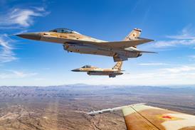
“We’ve been developing this technology for over a decade and the first flight test of a completely electrically actuated braking system was in 1998-99 in an F-16 flight test programme involving ourselves, the US Air Force, Lockheed Martin and Boeing,” says Goodrich wheels and brakes division president Brian Brandewie.

Goodrich has since been able to establish itself in the military electric brake arena through the supply of the first fully-integrated electrically actuated brake system, including controllers, to Northrop Grumman for installation on the RQ-4B Global Hawk Block 20 unmanned air vehicle. The first Block 20 is set to make its maiden flight in the next few weeks following its roll-out at Palmdale, California at the end of August. The UAV’s brake system includes several functions that will also feature on the 787 such as autobrake control, antiskid protection, differential braking and the important built-in test capability.

Goodrich plans to start deliveries of initial hardware to Boeing for test in the next few months, with first production shipsets due to be in Everett around mid-2007. Goodrich’s Troy site in Ohio will supply wheels and brakes, with its actuation systems unit in Cedar Knolls, New Jersey providing the electro-mechanical actuators (EMAs), which replace the hydraulic pistons and which apply the clamping loads to the aircraft’s brake disks. Goodrich’s fuel and utility systems unit is developing embedded software for the controller components.

electric break system 
© Goodrich    
Goodrich pioneered development of the 787 electric brakes with flight tests of an experimental system on an F-16 in the late 1990s

Meanwhile, dynamometer tests are underway in support of obtaining system certification in September. These will include simulated performance stops and rejected take-offs as well as reliability tests and environmental and service wear evaluations.

Messier-Bugatti, in association with Sagem, is in the process of testing its own “brake-by-wire” system and believes the introduction of the technology marks “as much of a breakthrough for airlines as was the advent of carbon brakes 20 years ago”. The Messier-Bugatti system involves a power supply, brake control and the electric brake itself, all of which are connected to an electric brake actuation control (EBAC). The unit is made up of an electric motor, reduction gear, ball-screw and nut, a rotor carbon disk and a stator carbon disk.

“We have some deliveries to make to Boeing for its test rig, and of course for the first aircraft,” says Messier-Bugatti wheels and carbon brakes senior vice-president Francois Tarel. “We are supplying three main units, the nose wheel, main wheels and the brakes, which are controlled by the EBAC. This converts electrical signals into commands and drives the brakes, and has to be integrated into the entire system,” says Tarel. “This is being demonstrated by Boeing at the aircraft level so we need to begin this integration task quite early, and we delivered the first unit in August.”

The unit was delivered for tests to Crane Aerospace & Electronics, which is responsible for the brake control and monitoring system, as well as the power control modules. Production EBAC units, however, will “go directly to Boeing for integration in the electronic equipment bay during final assembly”, says Tarel.

Tests of the brake itself are meanwhile being run in France to obtain TSO (technical standard order) certification, with work being performed at Villeurbanne, the centre near Lyon responsible for research and development as well as carbon disk production for aircraft as well as Formula 1 racing cars. Tests on the nose wheel have meanwhile been completed “and we are now in the process of finalising the TSO certification process and submitting documentation for final approval,” he says. Tests of the main wheel, including rejected take-off and endurance tests, are on-going.

Smiths Aerospace is responsible for the brake control and monitoring system, one of three main work packages under an integrated landing gear system contract awarded in 2004. The brake control is a wireless-based system that detects wheel speed and pressure data, and combines it with information from the rudder pedal positions, throttle position and other sensor and avionics data to instruct the brakes what to do. “The beauty of what we’ve got is a brake system that is far more effective and accurate at very low speeds,” says landing gear and hydraulic system programme director Matt Cowlishaw. The company is also delivering brake control hardware and software between now and January to a brake test rig being set up by Boeing in Renton and combining equipment from Messier-Dowty, Messier-Bugatti and Goodrich amongst others.

Smiths is also developing the nose gear steering and landing gear actuation systems, as well as high-lift actuation systems and is “around 95% through design work,” says Cowlishaw. “We are already to deliver test hardware to the integrated systems lab [at Boeing], and we have already made interface equipment like the tiller and handles which we delivered in August. The remainder of the test equipment and the hardware will be delivered in mid-December.”

Smiths has set up a nose gear steering rig as well as a full-scale wing rig to test the gear and high-lift system actuation in Wolverhampton in the UK. The rigs, supported with equipment from Messier-Dowty and (in the case of the high-lift rig) Moog, are “typically what Boeing what have done in the past. But it’s good news for us, because it increases our experience and shows we are taking responsibility for those parts”. By careful electric control of a damper manifold, which both controls steering and reduces vibrations, Smiths believes the system will be protected from any shimmying. “We have a development rig at Wolverhampton for steering and shimmying and we’re doing the first tests on it as we speak,” adds Cowlishaw.

The standard gear actuation system is “software-based rather than mechanically linked, so this saves a huge amount of time in closing and opening, as well as in weight. It’s also real micro-second sequencing, and is quite a clever step forward from a control point of view,” he says. The landing gear actuation package includes an emergency, 3,000lb/in2 (207bar) alternative landing gear deployment system, which “opens the doors, releases various actuators and then locks into position”, Cowlishaw adds. The gear actuation system, along with the rest of the main landing gear, will also be tested in the landing gear actuation system (LGAS) test rig at Everett in January.

The high-lift actuation system powers, actuates and monitors the flap and slat system and includes power drive units, a transmission system and rotary actuation and braking devices.

787 landing gear truck beams 
© Messier-Dowty 
The first main landing gear truck beams for the 787 are machined at Messier-Dowty's Gloucester, UK site

Keeping it cool

Another system where Boeing adopted a more-electric approach is wing leading edge anti-icing, which traditionally has been performed using hot bleed air from the engines. GKN Aerospace, together with Ultra Electronics, are working together to develop an electro-thermal system that will be the first commercial aircraft application of technology previously used on the blades of military rotorcraft such as the AgustaWestland EH101 and Bell Boeing V-22 Osprey. The system will be based on electrically heated elements contained within a sprayed metal matrix held in place on the leading edges by a polymer composite material.

Initial trials of the concept in Boeing’s own research anti-icing tunnel in Seattle led to some tweaks in the configuration, but have otherwise confirmed the baseline design, says Sinnett. “We have altered the design a bit on the heating blanket, which has now been moved further aft on the underside of the leading edge of the slat. We ended up extending the coverage on the slat by around 25mm to reduce the ‘run-back’ ice, so we are basically carrying the heat back further,” he adds.

Although much of the advanced technology focus is on the more-electric push, significant improvements are also being made in more traditional areas such as hydraulics. In early 2006 Parker Hannifin ran the first production configuration 787 hydraulic pump at its design ratings of 5,000lb/in2 with zero load, and 4,750lb/in2 at full flow, marking a crucial step towards full-up testing and production go-ahead. The higher pressure system was selected to reduce the size of individual system components, and thus the weight of the overall system compared to a conventional hydraulic configuration which is usually rated to around 3,000lb/in2. Parker is supplying the entire hydraulic sub-system through its Kalamazoo, Michigan-based hydraulic systems division.

heated blanket 
© DKN Aerospace   
The DKN Aerospace/Ultra Electronics-developed electric anti-icing system consists of a heated blanket made up of elements embedded in sprayed metal matrix.  Here the surface is prepared before the heating elements are added.

Added improvement

The company’s Nichols Airborne division is meanwhile supplying liquid-cooling pumps and reservoirs for Hamilton Sundstrand’s primary electronics cooling air management system and smart pumps for the Hamilton Sundstrand APU. Parker’s gas turbine fuel systems division is working with General Electric on the GEnx combustor, and with Rolls-Royce on the Trent 1000 fuel delivery system. The parker air and fuel division is providing the Trent 1000 with the pneumatic suite.

For the hydraulic sub-system, Parker says it has completed delivery of all ‘Iron Bird’ rig equipment, which includes reservoirs, filtration manifolds, accumulators, miscellaneous valves, quick disconnects, and ancillary equipment. Parker is also responsible for developing and certifying the hydraulic system control and indication software that will run on the aircraft’s central computer system.

The 787-8 is designed to have a maximum useable fuel volume of some 126,900 litres (33,530 USgal) within a maximum take-off weight of 217,725kg (480,000lb).

Goodrich provides the fuel quantity indicating system (FQIS), which senses the density and level of the fuel in wing and centre tanks. “We also do a lot of software work and one is for the fuel system as well as for proximity sensing,” says Goodrich sensors and integrated systems division president Brian Gora. “We have fuel quantity sensors going to FHI for the centre tank and to MHI for the wing tanks. Historically we would have sent those direct to Boeing, so this is much more of a logistics exercise,” he adds.

“The proximity sensing system monitors the position of the landing gear, fuselage doors, cargo doors, and thrust reversers. The system includes 136 proximity sensors located throughout the aircraft, six proximity data sensor concentrators that digitise the sensor data, and a software package that provides position status and health information to the flight deck displays.”

Fuel system

FR-HiTemp, which was purchased by Eaton in late 2005, has also delivered the first set of fuel system pumps and valves to FHI and MHI in Japan for installation in the centre and wing tanks respectively. The fuel system pumps and valves package includes 47 different part numbers and 216 components, and is “powered by electrically driven pumps using twice the voltage of previous commercial aircraft,” says Eaton. The company’s HiTemp unit is also teamed with Hamilton Sundstrand and Carleton on the nitrogen fuel-tank generating system. ■

Source: Flight International