Flight International checks out the industry's first digital dual head-up guidance system to be certificated for Category 3 touchdowns

Peering through the combiner, I could easily pick out the vivid green symbology against the grey concrete of the ramp at Portland International airport, and the equally dull early morning overcast and wondered how clear these symbols would be when flying above the cloud in the bright August sunshine. I would soon find out. Flight International had been invited to fly the world's first digital head-up guidance system to enter civilian service, and the first to be installed in a dual system on a commercial aircraft in revenue service. The Rockwell Collins HGS 5600 was mounted in the flightdeck of an Embraer 190, and final certification flight tests had been completed the day before our demonstration sortie.

HGS4

hgs3

HGS2

A  view through the HGS during a hand-flown approach to runway 28R.  The dashed 3 degree glideslope reference line is aligned to the runway indicators and the guidance cue overlies the flight-path symbol 


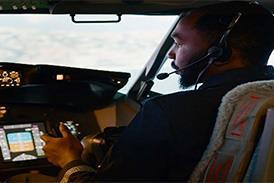
In the left-hand seat was Guilherme Cara, Embraer lead test pilot for the E-190 HGS certification effort, while occupying the jump seat was the Brazilian company's test pilot and human factors expert Mozart Louzada, a US Air Force test pilot school graduate and NASA-selected Space Shuttle astronaut candidate. As I took the right-hand seat, the first impression was the unobtrusive installation of the overhead unit (OHU), which blended inconspicuously into the overhead space.

Cara showed me how to unstow the combiner to its operating position by pushing a release lever and lowering the glass until it snapped into place. I removed its protective cloth and unlatched the sun visor, which I popped into the Velcro flap of the cover and put into a stowage shelf below the primary flight display (PFD) on the instrument panel. The action of snapping the combiner into place automatically turns on the OHU power supply, and symbology was projected on to the glass.

Display brightness

The brightness of the display could be altered by twisting a knob on the mounting supporting the arm, which holds the combiner in place. Brightness could be changed either manually or automatically, the latter through signals taken in by an ambient light sensor.

While Cara started the engines, Louzada showed me how to use the multipurpose control and display unit (MCDU) to enter runway data for Portland, as well as to select different symbology from the menu. The HGS page on the display unit provided inputs for runway length, elevation, combiner mode and a further function called HUD (head-up display) A3.

Combiner mode provided a choice between Auto, Declutter or Full, with Auto automatically removing airspeed and altitude tapes as well as the horizontal situation indicator (HSI) display during approach. Declutter, as this suggests, provided the option to remove the tapes and HSI during any phase of flight, while Full allows the crew to restore or maintain all the symbology after either an automatic or manual removal of the tapes and HSI. The HUD A3 provides an on/off selection for the crew to choose either the HGS or the flight-guidance control system as the source of guidance during an approach.

Taxiing out to runway 28R at Portland I used the markings on the HGS ground localiser deviation scale as a purely visual reference point to help me track along the taxiway's yellow centreline marker. It took a few seconds for me to see that some elements at the periphery of the display were sliding in and out of view, so I corrected my seating position to compensate.

Entering the runway behind a landing Boeing 757, I lined up on the centreline and stopped. Cleared for take-off, Cara told me to advance the throttles to the stops and not to touch the brakes. The view through the combiner had by now automatically changed to low visibility take-off display (LVTO) mode with a ground roll guidance cue. The change occurred as soon as we lined up and our heading and selected course for departure had come within 15° of each other. Other factors that kick LVTO into action include the Nav 1 and 2 receivers being tuned into the instrument landing system (ILS) frequency for the departing runway and the runway length being set correctly into the MCDU.

As the E-190 accelerated swiftly towards our V1 speed of 129kt (240km/h), I focused on keeping the HGS ground roll guidance cue in the circular ground roll reference symbol (a small winged circle). Although visibility was fine and the aircraft tracked the centreline well as we rotated at 136kt, I could imagine how the enhanced situational awareness of the LVTO cues might help in bad weather or with an engine failure, or both. If the cue moved to the left, the pilot needs to put in left rudder to centre the symbols, and so on. A triangle appears beside the ground roll reference symbol if the lateral deviation exceeds 90m (27ft) from the runway centreline, with the triangle pointing the right way to correct the drift. Cara was, meanwhile, able to monitor the V-speed bugs, which are shown on the tapes running down the sides of the combiner display.

GHS 
Symbology was easily visible even in bright sunlight

At lift-off, the ground roll reference circle was replaced with the inertially derived flightpath symbol, which adds a small tail to the winged circle and displays the actual flightpath vector of the aircraft. The circular guidance cue, which is a smaller winged circle, appears as the aircraft climbs through 50ft. Guidance for the correct pitch attitude is provided by a dashed line called the take-off pitch reference line, which is positioned at a fixed pitch angle, dependent on flap setting. The idea is to position the aircraft reference symbol, a small "v" with wings, on the pitch reference line to establish the right pitch attitude.

Although the pitch reference line disappeared 3s after passing 50ft, the guidance cue helped me steer on course as we were quickly swallowed up by the low cloud and lost all external visual cues. To help maintain the best climb performance and ensure the correct pitch attitude and airspeed during the climb-out an arrowhead-like flightpath acceleration symbol hovers off the left wingtip of the flightpath symbol. The symbol represents the combined effects of thrust, drag and the air affecting the aircraft and is an instant clue as to whether the aircraft is slowing, speeding up or maintaining a steady-state airspeed. If the symbol dips below a line level with the flightpath symbol wing, the aircraft is decelerating and vice-versa.

Guidance cue

Climbing through cloud, I followed the directions of the guidance cue, which was instructing me - via inputs from Cara to the E-190's flight-guidance control system (FGCS) based on a standard "River 6 departure" from Portland - to turn north on the first leg of a right-hand circuit over the Columbia river and over southern Washington. The climb-out was a little rough, but I had no difficulty in following the guidance cues thanks largely to the fly-by-wire flight-control system and responsive trim. At around 4,000ft we suddenly broke through into brilliant sunshine.

E-190 
Flight tests of the HGS took place on one of the first E-10s.

Continuing our turn to the east, and turning on to a long downwind leg for a return to runway 28R, I noticed the symbology remained clearly visible despite the Sun almost dead ahead, and without the need for brightness adjustment. I followed the guidance cue and looked at the en-route display symbology. Cara showed me how to select autopilot, which allowed me to take photographs through the HGS, this being indicated by the appearance of the letters "AP" at the top of the combiner with LNAV and ALT flight director modes selected. Lateral deviation from the localiser was displayed on a course deviation indicator line within the HSI compass at the bottom section of the combiner.

Re-entering cloud and manoeuvring for a HUD A3 approach, a rising speed error tape expanded rapidly on the left wing of the flightpath symbol indicating I was flying faster than the target speed. As we rolled out and became established on the ILS, the speed bled off as Cara configured the aircraft for landing while I concentrated on manually flying the approach. All this time I was now following guidance cues generated by the HGS rather than the aircraft's FGCS. With HUD A3 selected "on", the E-190 can be flown manually for Cat 1, 2 or 3 flight director approaches from left or right seats.

During approach, with the combiner mode set to Auto on the MCDU, the display automatically decluttered and the airspeed and altitude tapes disappeared along with the HSI. Instead, altitude and airspeed were displayed as digital values near the flightpath, with ILS data also being shown.

Glideslope lines

At around 900ft we emerged through the base of the cloud layer, and almost at once the HGS told me I was above the proper glideslope, which was indicated by a dashed 3° glideslope reference line, and well to the left of the localiser as indicated by two vertical bars. The combined glideslope and localiser deviation lines form a convenient cross-hair effect, which I found useful in terms of situational awareness as I tried to follow the guidance cue's efforts to put me on course for the runway.

Although closing nicely on the approach I was still slightly above the glideslope and too far to the left as we passed through 700ft. Despite concentrating on the guidance cue, I had time to notice the bridge carrying the East Portland 205 freeway over the Columbia river, and that the visual approach slope indicators by the runway were spot on the glideslope reference line generated by the HGS.

At 300ft, a set of runway lines appeared on the combiner. Scaled to a width of 60m and a length of 2,440m, they are calculated by the HGS using altitude, attitude and ILS deviation data from the aircraft sensors and runway information from the MCDU. The HGS uses corrected data from the inertial reference system and calculates other potential alignment errors such as changes in magnetic variation to try and minimise conformal errors. The outline appeared slightly offset at first, but the lines gradually overlapped more of the real runway as we descended and provided a comforting sense of ground closure and overall situational awareness.

Aiming at a touchdown point 320m down the runway, as indicated by the guidance cue, the runway lines symbol disappeared at 60ft - this being the decision height below which the real thing must be in view. A split second later, as the aircraft passed through 55ft, a "+" sign, representing a flare command, rose from the bottom of the display and merged with the guidance cue at the point where I was meant to begin executing the flare.

As the autothrottle was not selected, the next message as we passed between 30ft and 15ft was an idle symbol to tell Cara to pull back the power. If the airspeed is greater than or equal to the selected airspeed, the message is displayed at 30ft. If the airspeed is less, then the altitude is decreased 1ft for every 1kt of airspeed below the selected airspeed to a minimum of 15ft.

With a satisfying "plonk", we settled on the runway and Cara told me to again firewall the throttles for a touch-and-go. The ground roll reference symbol had meanwhile reappeared on the combiner, and was again replaced by the flightpath symbol after take-off, this time for a 14min-long left-hand circuit. After a second touch-and-go, we completed the demonstration with a full stop landing.

Having spent only around 40min in an engineering development simulator flying the HGS 5600 the day before, I reflected that in a short time the ability to follow the guidance cues so carefully had improved not only my confidence, but also my landings in an aircraft type to which I was completely new. The demonstration helped underline the overall targets of the Embraer/Rockwell Collins effort, as Louzada explains. "What are you looking for as a manufacturer is passenger comfort. With the HUD we get a better approach and more precise touchdowns. It is also safer and, in the end, more economical." Cara adds that the HGS "is a tool that improves both the aircraft and the crew's performance. It means a lot more safety, and fewer diversions."

Simulator test

In the simulator I was able to test the HGS in more extreme situations, and was shown how it could not only decrease the chances of hard landings and tailstrikes, but also prevent unstabilised rates of descent during approach as well as provide a way out for recovery from unusual attitudes. In addition, and the flight also demonstated this, it showed the potential benefits of not requiring the pilot to transition to a different instrument during the highest workload times performing a Cat 2/3 approach.

Embraer and Rockwell Collins hope to achieve Brazilian and US certification for the HGS 5600 on the E-190 by the end of November. The clearance will allow crews from JetBlue Airways, which is taking aircraft with dual HGS installations, to hand-fly approaches to Cat 3A minima with a 50ft decision height and a runway visual range (RVR) of between 120m and 180m. The HGS will also enable take-offs in reduced visibility down to 90m RVR.

JetBlue is expected to phase in the HGS as a guide to touchdown for Cat 2 this year, and for Cat 3 around October 2007. Usto Schulz, vice-president of JetBlue's E-190 programme, says the system is expected to cut training costs as well as increase safety margins. He says E-190 flightcrews "will be able to fly every approach the same way, in good weather and in bad, from the left seat or the right seat, to ILS-equipped runways or on non-precision approaches".

Rockwell Collins Flight Dynamics Embraer programme manager Robert Irish says flight tests have proved the robustness of the design and shown that potential issues of moving from cathode ray tube-generated imagery to the liquid crystal display have been addressed. "One of the early issues was the brightness of the display and whether we should give it more. Over the last year we've doubled the brightness to around 2,300ft/Lamberts and we're taking steps to go even further than that." Irish adds that the solid-state system offers a more adaptable platform for developments in enhanced and synthetic vision, providing a guaranteed window into the flightdecks of the future. ■

Source: Flight International