Slightly more than a decade ago, the so-called very light jet category of aircraft promised to set the world of business aviation alight. But while a number of good aircraft were offered, the market simply never materialised as predicted – and certainly did not recover from the body blow of the 2008 financial crisis. Demand for light jets fared little better until a few years back, when Embraer’s Phenom 300 sparked an upward trend, while Cessna has also maintained a strong presence with its CJ3 and CJ4 offerings. It was against these big manufacturers that a small Swiss company shook up the market when the PC-24 was unveiled by Pilatus at Europe’s EBACE business aviation show in 2013.

PC-24 side c BillyPix

BillyPix

NICHE OFFERING

Pilatus’s view was not that it was entering a crowded market – rather, the company saw itself as developing something new: what it described as a super versatile jet. The promise was a light jet with a mid-sized cabin that could operate from unpaved strips. Initial deliveries were in executive configuration to fractional ownership operator PlaneSense, starting in February of 2018. Deliveries of medevac-configured PC-24s to Australia’s Royal Flying Doctors Service, which operates 35 PC-12 turboprops, followed from November.

Recently, FlightGlobal was invited to Pilatus’s base in Stans to experience first hand how Pilatus’s niche-busting PC-24 performs. The day prior to the flight was filled with briefings and the seemingly obligatory factory tour. Over the 28 years I have been a test pilot I have seen more factory floors than I care to remember, and truth be told I was not expecting anything of note from the proposed tour.

The feel of Pilatus’s facilities, however, was different – these were more like artisanal workshops. The one hall that did machining was filled with very sophisticated Grob CNC machines, which milled away in near silence. The only hall that was loud was where stringers were fitted to skins. In a nod to efficiency – labour being expensive in Switzerland – the PC-24’s fuselage is designed so a single person can do each rivet, with no bucking required. Building a jet aircraft is not a cottage industry, but individual skills were on display in every production hall. Pilatus has long traded on Swiss craftsmanship, and my tour of the production halls showed that PC-24 operators will not be disappointed.

PC-24 002 c BillyPix

BillyPix

FLYING ACE

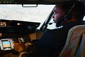
As part of my facilities tour I was able to spend about half an hour in a PC-24 cockpit. Accompanied by sales and marketing director Matthias Luder, I familiarised myself with the flightdeck. When I flew the PC-12NG three years ago, I was impressed by its Honeywell Apex flightdeck. For the PC-24, Pilatus has added several new features and now calls its avionics system the advanced cockpit environment (ACE). Similar to the flightdeck in a PC-12NG, it has four identical 12in LCD displays with integral bezel buttons positioned in a T configuration; primary flight displays (PFDs) outboard and two multifunction displays stacked in the centre.

ACE is based on the flight-management system and similar to what I use every day in the Boeing 737 and carries over a number of the Apex’s notable features: cursor control device (CCD) with tracking ball located aft of the thrust levers, resident wireless capability, vertical situation display and SmartView synthetic vision system. ACE adds some additional features that make it even more useful – it comes with a class-unique ring laser gyro inertial guidance system as standard, as well as a three-axis auto-pilot and autothrottle.

Pilatus did not just upgrade the avionics when it developed the PC-24. Like the PC-12, the PC-24’s primary flight controls are all manually actuated. The secondary flight controls are all electronically actuated, with the only hydraulics being a power pack for the anti-skid-protected main wheel brakes. The overlying electronic architecture is composed of two buses. The electrically actuated secondary flight controls are controlled by four, two-channel data concentration and processing units, which host control and monitoring channels running dissimilar software; further redundancy is assured by the use of separate sensors to determine commanded surface position and actual position.

The aircraft for our preview flight, registration HB-VVV, was the one I had done my cockpit familiarisation in. Its fuselage was festooned with several sizable Edelweiss flower stickers. As I followed test pilot and head of experimental testing Matthew Hartkop for the external pre-flight inspection I marvelled at the exterior fit and finish. While the PC-24’s configuration is like that of nearly every other business jet, it is in the details that beauty of this Alpine flower shows. The high-aspect-ratio wing (9.35) was developed using a DNA-like iterative process. The span features five different cross sections to provide lift for short-field operations, while allowing speeds up to Mach 0.74 at 4,500ft.

Unpaved field operations, the PC-24’s niche, drove a number of characteristics. The wing root needed be thick enough to stow the two-wheeled main gear assembly required for softer surfaces. The large-span, two-panel double-slotted flaps are unusual, as they do not use guide tracks. Bruno Cervia, deputy chief executive and head of research and development, says the trackless design ensured gravel and other debris would not hinder flap operations. Also of note were the four spoiler panels on each wing. As currently configured, the two large inboard ones are for lift dump on the runway, while the two smaller outboard panels are multifunction roll/speed brake.

THRUST UP

Inspection of the aft lefthand side of the fuselage revealed what is perhaps one of the PC-24’s biggest competitive advantages, the cargo door. Fully 1.25m x 1.30m (4ft 1in x 4ft 3in), there is nothing in its class that comes close. Inside the cavernous aft cargo compartment is an adjustable frame and net baggage restraint system. For outsized cargo, seat rails run the length of the cabin to secure larger items.

Williams FJ44 engines are mounted conventionally on the tail. The engine rotor burst zone is aft of the entire baggage area, allowing in-flight access to the compartment. Pilatus fabricates most of the PC-24’s structure, including the engine nacelles. The exhaust end of the nacelle is not flat when viewed from the side – rather it is concave, with the top protruding further than the bottom. Cervia said this was done to use the Coanda effect – the tendency of a fluid stream to adhere to a convex surface, seen for example in the airflow following the curved upper surface of a wing – to vector thrust upward. At take-off power settings the exhaust stream is turned upward by a full 3°. This counters what would otherwise be a nose-down pitching moment caused by the high mounted engines. Harnessing the Coanda effect allows for a smaller horizontal stabiliser and elevator, reducing weight and induced drag. One beauty of this design is that at cruise power settings the turning effect of the exhaust lip is reduced, giving a more efficient thrust line.

With the walk-around complete, I strapped into the lefthand seat and used the pillar-mounted alignment balls to move the manual seat so that I was comfortably seated at the design eye position. The thrust levers fell readily to hand with the CCD conveniently located just aft on the centre pedestal. The ACE flightdeck was well arranged with a small overhead panel that contained electrical system control, lighting switches and two rotary engine controls. As mentioned earlier, the forward instrument panel was nearly identical to the PC-12 NG’s.

On the centre pedestal, below the lower multifunction display, was the large multifunction controller. It contained alphabetic and numeric keypads, as well as several shortcut keys. It also had a joystick for cursor control, and four arrow keys that moved the cursor between displays, duplicating CCD functions. The sidewalls were remarkably clean, housing oxygen masks and a row of seven circuit breakers on the lefthand side. All the other circuit breakers are remotely located and accessed through the flight management system synoptic pages.

PC-24 dashboard c BillyPix

BillyPix

After completion of before-start items, confirmed with the intuitive electronic checklist, the right engine was started. Once it was stabilised, the flaps were extended to 15° and a control sweep completed before the left engine was started. The PC-24 has manual pedal-controlled nosewheel steering; direct control up +/-17° with angles up to 60° available by using differential braking to enter the castoring region. During the taxi to runway 06 at Buochs, I found that slow-speed 90° turns were difficult to accomplish, as transition to the castoring region was needed. Hartkop recommended using differential thrust to facilitate 90° turns, which made the task somewhat bearable for this neophyte PC-24 pilot. Once rolling, turns up to 45° were easily accomplished, as was tracking of taxiway centrelines.

PC-24 take-off c BillyPix

BillyPix

CIRCLING BURGENSTOCK

Once lined up and cleared for take-off I advanced both thrust levers to mid-range, where the autothrust engaged, and set take-off thrust of 94.7% N1. Hartkop called out V1 followed directly by “rotate” at 95kt (176km/h) indicated airspeed (KIAS). Approximately 15kg (33lb) of aft yoke was needed to rotate the aircraft, where I captured an initial pitch attitude of 15°.

Certificated for single-pilot operations, I called “gear up” to keep Hartkop in the loop as I raised the landing gear. Passing 130KIAS I retracted the flaps, again calling out my actions. Once the PC-24 was in a clean configuration, I pulled up into a climbing turn to fly crosswind over a finger of Lake Lucerne, turning downwind at 4,000ft mean sea level/2,500ft above ground level to parallel the mountain ridge with the Burgenstock resort near its peak.

Passing Burgenstock I started configuring and descended over the narrowing of Lake Lucerne, just north of Stansstad. Hartkop suggested I shoot to be 2,700ft mean sea level/1,200ft above field elevation at 130KIAS with gear down and flaps 33° there. The circuit around Stansstad was in essence a 135° base-to-final turn, rolling out aligned with the runway at 2,100ft mean sea level/600ft above field elevation. Time on the 4° glidepath final, as defined by the precision approach path indicator, was fairly short. The Williams engines and the PC-24’s inherent speed stability on final allowed me to capture and hold target speed of 98KIAS; not a trivial task given the varying winds whistling down the various passes and narrows. Thrust levers were retarded at 30ft above ground level, with the flare manoeuvre started at about 20ft.

It is not clear if it was my piloting skills or the trailing-link landing main gear with its low-pressure tyres, but it was a smooth touchdown. Once the nosewheel was grounded I set the thrust levers to mid-range, while Hartkop set the flaps to 15° and stab trim to the take-off band for our touch-and-go. When Hartkop called “go” I advanced the levers and rotated for liftoff, passing 95KIAS. The next circuit and touch-and-go at Buochs was again a joy to fly, given the PC-24’s predictable handling qualities and the wonderful scenery.

After completion of the second touch-and-go at Buochs, we left the pattern and climbed into a medium-altitude block to sample the Pilatus’s low-speed handling characteristics. Level at 16,000ft I did a number of steep turns (45° angle of bank). I held 130KIAS, 25KIAS above the 7,940kg aircraft’s Vstall of 105KIAS.

The aircraft was still quite responsive in roll with a bit of rudder needed to co-ordinate the turn. While synthetic vision was not much use at altitude, I did appreciate its edge-to-edge attitude information, with the flightpath vector making altitude control an easy task. What was neat was how the synthetic vision display decluttered at bank angles greater than 45°, alerting the pilot of the steep bank.

Next we did two stalls, one in a clean and the other in a landing configuration. These manoeuvres would sample the PC-24’s stall warning protection system. The system operates in two phases: stall warning phase and stick pusher phase. Stall warning includes an aural “stall”, visual red “STALL” on the PFD and the tactile stick shaker. Should the pilot ignore these warnings, the stick-pusher uses the autopilot servo to command nose-down elevator until the sensed stall condition is alleviated. The PC-24 has two angle-of-attack vanes/sensors and cross checks their values before declaring a stall condition. In both the clean and landing configuration approach to stalls, the PC-24 was stable in all three axes. There was little airframe buffet but the ACE-generated warnings were sufficient to announce the low-speed condition. In both instances stick-pusher activation forced the yoke forward and pitched the nose down to break the stall.

Satisfied with the PC-24’s slow-speed handling qualities we started a climb to the aircraft’s ceiling, 45,000ft. Once level there I stabilised the aircraft at M0.65 for a long-range cruise point. Total fuel flow was 850lb/h and the 7,260kg aircraft clipped along at a true airspeed of 372kt. Book data for high-speed cruise at the same conditions increases fuel flow to 970lb/h while pumping the speed up to M0.74.

Next Hartkop would demonstrate an important safety feature of the PC-24 – its emergency descent mode (EDM). EDM is armed only above 30,000ft with the autopilot engaged, and triggered when cabin altitude exceeds 9,600ft. Designed to descend the aircraft to prevent a hypoxia-induced loss, it starts a descent at Mmo/Vmo to 15,000ft mean sea level while turning 90° off course. Simultaneously it wakes up the autothrust, if not engaged, to set IDLE thrust. With clearance for descent from air traffic control, Hartkop triggered the EDM. I watched with satisfaction as we stabilised in an IDLE power 4,000ft/min (20m/s) descent to safety.

Satisfied with EDM operation, I disengaged the autopilot and hand flew the aircraft, turning south towards Lugano for a steep approach and landing. Hartkop loaded the inertial guidance system (IGS) runway 01 into the flight-management system. The IGS approach offers instrument-landing-system-like guidance but with a 6.65° glidepath. Pilatus plans to offer a coupled approach capability for steep approaches like this, but the software load on our preview aircraft meant I would get to hand fly it.

STEEP APPROACH

Fully configured on final at 110KIAS (Vtgt) our rate of descent was 1,100ft/min (20kt headwind giving a 90kt ground speed). I followed the flight director’s guidance in the PFD’s synthetic vision display. Passing 1,000ft Above ground level I shifted my reference outside the aircraft, aiming at the threshold. I was careful not to follow the precision approach path indicator, which was set to a shallower visual approach angle of 4.20°. As with the approaches at Buochs I retarded the thrust levers to IDLE at 30ft. The flare manoeuvre was also begun at 20ft, but at a faster rate to arrest the higher sink rate.

Touchdown was fairly soft, about 275m (900ft) from the threshold. Maximum wheel brakes were applied once the nosewheel was on the runway. The anti-skid cycled as the effective brakes brought the PC-24 to a stop just 350m from the touchdown point. After a short back taxi on the runway, we parked the aircraft for a short break.

The second part of the preview flight was a whirlwind tour of airfields during our return to Pilatus’s Buochs airfield. After departure from Lugano’s runway 01, our first stop was at Grenchen, a small airfield just north of Bern. The airport is serviced by VHF omnidirectional range and RNAV approaches to runway 24. Hartkop loaded the RNAV runway 24, but as the winds favoured runway 06, we would visually circle for a touch-and-go on the 1,000m x 23m paved surface. During the approach and manoeuvring in the visual environment I found the standard traffic alert and collision avoidance system (TCAS II) helped us get eyes on aircraft in the congested area. On final Hartkop reminded me that it was a narrow surface – so it was important to stay on centreline and not flare late.

As with the previous landing, the PC-24 settled gently on to the runway, where Hartkop hurriedly reset the flaps and trim for the touch-and-go. Once airborne I cleaned the aircraft up and turned towards Militarflugplatz Emmen, 9nm (16km) north-northwest of Pilatus’s sairfield at Buochs.

Hartkop guided me through the installation of the instrument landing system DME Z runway 22 at Emmen. The approach would be hand flown. On a long final Hartkop simulated a one-engine inoperative event by pulling the number two engine to IDLE. Configured on glideslope with flaps set to 15°, only a small amount of left rudder was needed to maintain co-ordinated flight at 107KIAS (60% N1 on the good engine). Initially I trimmed the rudder forces out, but then centred the rudder trim for the remainder of the approach. Hartkop called “go around” at minimums. I rotated the PC-24 to a 10° nose-up attitude as I moved the left thrust lever to take-off power (95% N1). I fed in left rudder as the power increased, with approximately 45kg of force needed to maintain co-ordinated flight at 120KIAS. To ease pilot workload in the event of an engine failure, the PC-24 has a rudder bias system. If an engine failure is sensed below 2,500ft Above ground level, the autopilot’s yaw damper servo deflects the rudder in the direction of the good engine. The amount of deflection is approximately one-third of that needed for co-ordinated flight. After a heads up, Hartkop disabled the rudder bias so I could feel the unaugmented forces. Every bit of 65kg of force was needed to maintain co-ordinated flight.

Satisfied with the PC-24’s handling qualities with one engine inoperative, I advanced the right thrust lever to terminate the exercise. I found the rudder bias system was a useful aid for the pilot when responding to an engine failure, but not a feet-on-the-floor solution to counteract asymmetric thrust.

With both engines in use and the PC-24 cleaned up, we turned towards Buochs for a maximum-effort landing. Flaps were again set to 33° with a Vref of 96KIAS. I floated a bit in the flare, touching down further from the threshold than desired. After alighting on runway 06, wheel braking cycled the ­anti-skid and slowed the PC-24 to taxi speed by taxiway D (650m from the threshold). After a short pause to allow our photographer to get in place, we taxied back to runway 06 for another take-off and two more visual circuits around Burgenstock and over Lake Lucerne. I was saddened when we received word the photographer had gotten all the shots he needed, as my pattern fun had come to an end. Taxi back to parking was a breeze, save for my less-than smooth low-speed double 90° turn in the close quarters of Pilatus’s ramp.

During my whirlwind tour of Switzerland I was at the controls of the PC-24 for more than 3h 30min. In that time I was able to see how it flew at the extremes of its flight envelope. The medium-altitude stint showcased its docile low-speed handling characteristics, while the brief time at its ceiling demonstrated the ­PC-24’s safety-enhancing EDM feature. The extensive pattern work gave me a good feel for its well-harmonised control forces, as well as the workload-reducing rudder bias system.

The PC-24 is a winner when judged from the pilot’s seat, but its large cabin and sizable cargo door are huge differentiators in this segment. Add to this steep approach and unpaved field capabilities, the PC-24 is a true all-rounder. With the PC-24 Pilatus has fielded a high-speed stablemate to the PC-12, moving its sizeable cabin between similar strips but 155kt faster.

Find all the latest news, pictures, video and analysis from EBACE 2019 on our dedicated page.

Source: Flight International