Flight International's test pilot deliberately gets into some awkward situations in an Atlas Impala as he finds out how training is advancing

Test pilot schools worldwide are providing more rigorous courses and higher technology to meet the increasingly sophisticated demands of 21st century flight testing. Nowhere is this more evident than in Mojave, California, home of the National Test Pilot School (NTPS) and site of the only non-governmental school in the USA.

One of the workhorses of its fleet is the Atlas-built Aermacchi MB326M Impala, a tandem-seat straight-wing trainer/light attack aircraft. The NTPS Impalas are ex-South African Air Force aircraft, powered by a single Rolls-Royce Viper Mk22-1 turbojet. Flight International was invited to fly a medley instructional sortie - touching on loads, flutter and high angle-of-attack (AoA) - in a specially modified Impala.

The instructor for the sortie was Gregory Lewis, deputy director of the school. Lewis is a graduate of the US Air Force Test Pilot School (USAFTPS) and he was involved in some of the early developmental testing of the Lockheed Martin F-16. He also flew a Boeing F-15 Eagle as part of a research effort. Our mission was monitored in real time from a ground-based telemetry (TM) station manned by George Cusimano, senior flight-test engineer instructor and another graduate of the USAFTPS.

The Impala used for our sortie, N155TP, was instrumented as a loads-and-flutter aircraft. The data-acquisition system recorded basic flight parameters and control positions, as well as structural loads at various points. In addition, the aircraft had two dynamic response exciters recently installed, one near each wingtip on the aft wing spar. The exciters used a variable-speed unbalanced rotor to impart force into the aircraft structure. The exciters were controlled from the rear seat of the aircraft, while the exciter enable and kill switch was in the front seat. While the pilots would feel aircraft response in the seat of their pants, the TM station could see detailed real-time aircraft response to control and exciter inputs.

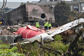
The first test point was a vertical-stabiliser load investigation. For this test, Cusimano monitored bending moment on the vertical stabiliser's spar at its root. This area of aircraft structure received increased scrutiny following the crash of an American Airlines Airbus A300-600 in November 2001. As has been widely reported, the vertical stabiliser on the A300-600 separated from the aircraft, which then crashed, killing all 260 on board and five on the ground.

The exercise in the Impala is in no way intended to fuel the debate as to why the A300 lost its vertical stabiliser, rather it was developed to teach techniques for the evaluation of compliance with applicable governing regulations. Under US FAR Part 25 airworthiness standards for transport category aircraft, the structure of an aircraft must be designed to withstand loads resulting from specified manoeuvres.

Rudder deflection

The yaw manoeuvre specified in these rules dictate the aircraft initially be in a zero-yaw, unaccelerated condition. The rudder is then suddenly displaced either to its stop or the position resulting from a specified force input: 136kg (300lb) below manoeuvre speed and 90kg above.

The yawing moment generated will cause the sideslip angle (beta), with wings level, to initially exceed the eventual equilibrium beta. Once the aircraft is stable at the equilibrium beta, the rudder is then suddenly returned to its neutral position. It is the loads generated during this manoeuvre, over a defined speed range and varying load conditions, that determine if the structure is in compliance with the FARs.

The Impala was stabilised at 180kt (330km/h) at 18,000ft (5,500m) altitude. Holding wings level, I rapidly displaced the rudder to the right, attaining roughly 18° of deflection at the mechanical stop. As shown in the diagram above, the maximum dynamic tail load was experienced just after full rudder deflection was reached. The bending moment reached 26,000in-lb (3,000Nm). Suddenly returning the rudder to neutral, after 1s at full deflection, generated a load of 24,000in-lb.

Focusing on the direction of the bending moment generated, right rudder caused the tip of the vertical stabiliser, when viewed from behind, to bend to the right. The lift generated by the stabiliser and rudder bent the top to the left but this was overcome by the side airload imparted on them by the large sideslip angle.

The next and more interesting test point was set again at 180kt and 18,000ft. This time the beta generated by full right rudder displacement would be allowed to stabilise, as called for in the FAR rules. From this stabilised condition, the rudder would not be returned to neutral; rather it would momentarily be displaced about one-third of the way to the left before being returned to neutral. As shown in the diagram below, from 16° right the rudder was rapidly reversed to 6° left before being centred. The peak bending moment of 35,000in-lb, again tip-right when viewed from behind, is attained 0.2s after the rudder passed through neutral going from right to left. This load is fully 35% greater than that attained during the initial rapid right rudder input in the first test point. In addition, it is five times greater than the 7,000in-lb moment generated at the steady-state beta with full right rudder.

As shown by the above, one can summarise that dynamic stabiliser loads are far in excess of stabilised ones. Perhaps even more relevant to understanding of the Airbus A300-600 accident is the effect a rapid rudder reversal has on vertical stabiliser loads. Returning the rudder towards neutral from full displacement decreases the aerodynamic lifting force that had mitigated the side airload imparted by large beta, and caused the stabiliser to experience a higher bending moment.

Additionally, as the rudder swings through neutral on the reversal, it starts to generate a lifting force that reinforces the beta-induced side airload, increasing the bending moment by 35% in the case above. The above load increase was generated by a rudder reversal of only 6°. It is not hard to imagine that dynamic loads generated by a full rudder reversal would far exceed that.

Dynamic response

After completion of the stabiliser loads investigation, we next explored the Impala's dynamic structural modes. Aerodynamic forces can couple with an aircraft's natural structural frequency to excite a dynamic response. The designer's concern is that aerodynamic forces may excite and reinforce a structural response that is unbounded. Much like pushing a child on a swing, if the aerodynamic forces are in phase with the structure, the oscillations will get larger and larger and, unless these oscillations are damped out, structural failure may occur.

Through ground vibration testing, the NTPS staff had determined the Impala had a number of structural vibration modes at and below 15Hz. The first of three was the first wing bending mode at 6Hz. This mode is characterised by the wingtips moving up and down in unison. The second is a torsional wing bending mode at 12Hz. In this mode the wingtips twist asymmetrically, the forward left tip going up while the forward right tip is going down. The third and final mode is wing torsion mode coupled with the fuselage's first bending mode. This mode was projected to occur at 15Hz.

Underwing exciters

Level at 20,000ft and 160kt, Lewis engaged the exciter at 6Hz. Little aircraft response was felt and the frequency was increased to 12Hz. A very slight amount of asymmetric wing torsion, tips rotating 180° out of phase, was felt. The frequency was then increased to 15Hz, where definite torsional wing-tip motion could be felt and seen. On the TM station's command, I killed power to the exciter and the oscillations immediately damped out.

Had the oscillations continued without the exciter driving them, further investigation would be needed to characterise the phenomena. If the oscillations were bounded at an acceptable level, then corrective action may not be required. However, if the oscillations had continued to grow in magnitude, either structural changes would be required or flight envelope restrictions imposed.

Upset recovery training has become a hot topic in the transport world. In the past, it was nearly impossible to get a pilot's licence or progress far in one's career without having done aerobatics or spinning an aircraft. After completion of the flutter investigation, we found we had enough fuel for several spins before returning to Mojave. The last aircraft I had spun was Aero Vodochody's L-159 in Prague nearly five years ago, so I was eager to "get out of control".

The first spin was from an upright entry, with full aft stick and full right rudder being applied at the first indication of stall. The entry was fairly dynamic, with the nose remaining above the horizon until after the completion of the first turn. The nose dropped well below the horizon and a steady yaw rate to the right developed. After completion of the third turn, recovery controls were input: left rudder to stop the yaw and neutral longitudinal stick to break the stall. The aircraft recovered to normal flight in a steep dive a quarter-turn after application of recovery controls. The next and last spin was again from an erect entry, but this time the stick was pushed fully forward and to the left to enter an inverted spin. As the aircraft started to tuck under, full right rudder was put in. The entry was more dynamic than the upright spin and slightly more disorienting. In an inverted attitude a right yaw rate developed with the nose below the horizon. Prominent pitch and roll oscillations continued throughout the three-turn spin. Recovery was again affected by putting in rudder opposite the spin, left in this case, and centring the stick. Spin recovery took one full turn, with the aircraft ending up in an 80° dive.

Simulated engine failure

Once in level flight, Lewis set the throttle to 60% and extended the speedbrake half open to simulate an engine failure. I slowed the aircraft to 150kt for a gliding recovery to Mojave. As we were fairly high and close to the field, a number of 360° turns were required to descend to a high key position overhead runway 26. The ability to execute a flame-out landing is an essential skill for any single-engine pilot, perhaps even more so for a test pilot conducting engine or high angle-of-attack tests. Once on downwind, the gear was lowered and flaps set to full for a low approach. Even with a 35kt headwind, I found the Impala easily allowed me to set and keep the desired aimpoint for the low approach. At around 20ft above the ground, I advanced the power, retracting the gear and flaps as the aircraft accelerated. At 150kt, I started a right-hand climbing turn to downwind. The visual final approach to the full stop was flown at 110kt with full flaps.

After the flight, Cusimano joined us for the debrief. Using TM data he critiqued control inputs and discussed resultant aircraft response. The vertical stabiliser loads diagrams are illustrative of what can easily be accomplished post-flight with appropriate data files and a spreadsheet. The flutter exercise was productive, but larger weights in the dynamic response generators may have elicited a larger structural response. The two spins, the inverted one in particular, reminded me how disorienting an unusual attitude or out-of-control situation can be. During the one-hour flight in the Impala I was reacquainted with the rigours of flight test, while gaining an appreciation of the NTPS curriculum.

Fight test is a demanding discipline and the efforts of several schools and the Society of Experimental Test Pilots elevates the community's professionalism so it can be conducted safely and efficiently.

8059


8060


Length

10.6m

Mean take-off weight

2,930kg

Wing span overall

10.56m

Powerplant

1 x Rolls-Royce Viper

Height

3.72m


@4,000lb thrust

 Service ceiling

40,000ft

 Range

 2,100km

 Weight empty

 1,660kg

 Maximum speed

480kt


MICHAEL GERZANICS / MOJAVE, CALIFORNIA


Source: Flight International